Thomas ELTZER, Denis CAVALLUCCI, Philippe LUTZ, Nikolai KHOMENKO. Contribution to early stages analysis: a framework for contradiction’s complexity representation. ETRIA, 2004
It is universally acknowledged that actual industrial situation regarding problem solving stages is of a critical matter for R&D robustness. A technical situation that causes inefficiency is stated as an “unsolvable problem” and treated as “best possible compromises”. In fact they are the result of a complex situation where mental inertia leads the designer’s attitude. Regarding the way TRIZ’s theory addresses problem, it is also now worldwide recognized that a contradiction should be solved in a “non compromised way” in order to move toward inventiveness in accordance with laws of system evolution. Nevertheless, the stage of gathering data in such a shape that the initial fuzziness is reduced to an efficiently built physical contradiction remains unclear in the framework of classical TRIZ. Among others, this situation creates now an obvious obstacle to TRIZ’s credibility in organizations. Our paper proposes a representation of a complex given industrial situation in a meta-net of contradiction in order to prepare any problem solving stage with the correct scientific models of physical contradictions and their inter-relations. An example of shaping the meta-net of contradiction in injection molding will be shown through a case example.
Keywords:
Contradiction network, Injection molding, design, knowledge, OTSM-TRIZ
1. Stating the global problem and our proposed methodology
Technical artefacts are becoming increasingly sophisticated as technology evolves and competitive pressures pose new constraints on firms, especially concerning their ability to innovate (at the product or process level) at an ever increasing pace. The result is the need for firms to rebuild design potential, both in terms of human skills and methodological expertise.
A new situation is affecting the designers of these artefacts. It can be summed up as follows: are the tools and methods developed to aid the designer in his tasks still appropriate in the context briefly outlined above?
Two fundamental aspects make us think this is not the case:
- The gap between the rate of requests for human creativity and its actual capacity;
- The gap between the scopes of knowledge required in view of the level of complexity, and the inherent ability of a human group within a given organisation.
Contemporary designers are faced with a two-fold dilemma – that of having to ensure design tasks in a context where:
- The tools and methods available to assist them were developed within a context of optimising quality, as imposed in the 1960s-1990s. This means they are not always adapted to meet the requirements of current design tasks which are more focussed on optimising creative potential (Shaw, 1986) leading to higher efficiency in terms of inventiveness in the design act within the company (Holtj, 1992);
- The complexity of the artefact and the scope of knowledge required make their own creative capacity inadequate. This limitation is accentuated by the fact that a truly inventive act is often measured by the following yardstick: external knowledge (i.e. unknown at that time by the industrial sector in which the designer works) is technologically transferred to the designer's own field, thereby making the creative act inventive.
All design acts are carried out as cognitive acts encouraging the designer to solve a contradiction introduced by his act. This essential notion in TRIZ stipulates that the contradiction symbolises the obstacle which has to be understood and solved to enable the technical system to evolve in keeping with the laws. While cognitive reflexes often drive designers to a compromise solution, Altshuller purports that compromise does not arise from an inventive approach and that to move in the direction of inventiveness, the designer must refuse compromise despite his psychological inertia to solve the dilemma posed by the contradiction. After the work of Nikolaï Khomenko on OTSM-TRIZ (Khomenko, 2002) , it has been stated that the level of complexity involved in designing an artefact implies that a network of contradictions (also called problem flow technology) representing the corelation between problems and their subsequences should be built up in order to place the designer face to face with the challenges he has to raise.
The aims of this presented work is then to introduce from a theoretical and practical angle how we intend to represent a complex situation in a graphical form in order to efficiently manage problem solving process. The practical viewpoint will be given by an application in injection molding.
2. Complexity of design in injection molding
2.1 The particularities of injection molding technology
Injection molding design consists mainly of part design, material selection and mold design (Rosato, 1995). The machine used to process the plastic material is seldom designed for a specific project, but chosen out of the resources of the company. Part, material and mold are defined in order to reach some specific requirements: mechanical (stiffness, shock…) chemical (toxicity…) functional (easy to use, rigid…) processing (easy to manufacture, low tool wear…) cost (low prize of material, low mold cost…), see (Beiter et al, 1995). Requirements can be drawn out of the product life cycle (Chakravarty, 2001).
We can underline the following particularities:
- These three entities have to be designed one according to the other. For example: the mold has to be designed according to the part design; the part has to be designed according to the chosen material;
- Each can be adapted according to the requirements. For example: in order to eliminate sink marks or flashes, it is possible to change either the part design or the mold design; in order to reduce wear of feeding chanels, it is possible to change either the plastic material or the mold material;
- Requirements can be common or specific. For example: some processing defects, or processing time are relevant to both the material, the part and the mold whereas the amount of material is only relevant to the part design.
Therefore, the design task can get really complex: many technical contradictions can appear between requirements, and many physical contradictions can appear on parameters of the three designed objects. All those contradictions are linked, and generate a network that should be investigated in a smart way to converge rapidly to the definition of the key issue of a specific situation.
2.2 Design knowledge
Many scientific fields have to be considered within injection moulding design. The first and obvious is chemistry, which can explain the properties of molecules (interaction with environment, with mold, with user…). The second is rheology, and explains all the consequences of material flow within processing (molecules orientation, cristals creation, shear heat…). The third one is mechanics, used to preliminary and detailed design of parts (dimensions, frequency of use and force application…) or mold (thickness to reach a certain rigidity…). A fourth one can be named “technological knowledge” and is built on the experience of designers (capabilities of standard product configurations…). Furthermore, within each of these fields, many researches items are being conducted in order to facilitate, as a final objective, efficient design. Therefore, during problem solving, each field should be investigated and well understood in order to not miss the solution, but only the field of efficient solution needs to be known in order not to grow the complexity of the needed knowledge, and to reduce time of solving.
2.3 The methodology employed to represent this knowledge in a metamodel.
- Creating an influence network
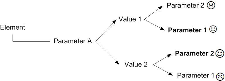
In order to solve this contradiction we propose to structurise the required knowledge beforehand, in a way that can be usefull for TRIZ application (Altschuller, 1973). In order to harmonize design field and TRIZ paradigms, we propose to precise the contradiction pattern (see Figure 1) the following way (Eltzer, 2004):
- “Element” is whole or part of design objects (it can be obtained through analysis with first law of technical system evolution);
- “Parameter A” (which we will name “physical parameter” of the contradiction) is a parameter defining the designed object. It cannot be evaluation of the object. It represents what the designer can directly change. It can have different levels in design (conceptual, preliminary, detail (Pahl&Beitz, 1996)). It is the consquence of only the designer choice. If the physical parameter fits those conditions, it is named “active parameter”;
- “Value 1”, “Value 2” are possible values of the physical parameter, each of them defining a specific system;
- “Parameter 1”, “Parameter 2” (which we will name “technical parameters” of the contradiction) are criteria used to evaluate the design project. They can be relevant to design object (manufacturing precision for example) or to anything else (environment harms for example). They cannot be choices. They can represent constraint, functions, evaluation. If technical parameter fit those conditions, they will be named “evaluating parameter”;
- “J”, “L” are values of technical parameters as consequence of value of the physical parameter.
Figure 1: Contradiction pattern
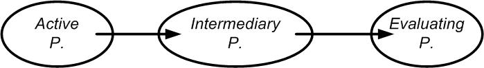
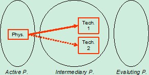
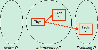
 The value of active parameter is the consequence of only the designer choice, and relations between designed objects have to be represented this way. In order to integrate precise knowledge and sharp explanation of conflicts, we propose to introduce “intermediary parameters” between physical parameter and technical parameters of any contradiction (Figure 2):
Figure 2: Intermediary parameters
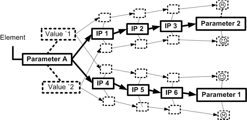
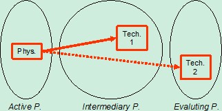
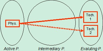
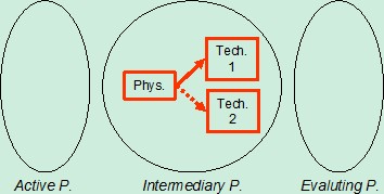
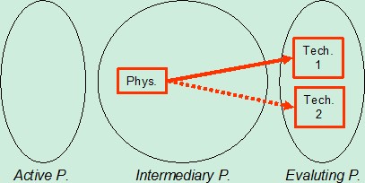
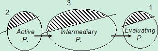
These three families of parameters are linked with objective laws (presented as arrows on Figure 2). These objective laws are the bases of the knowledge required to design. Intermediary parameters can belong to more than one route from physical to technical parameters. As a consequence, a complete network of parameters is built on the bases of three families of parameters (see Figure 3), in order to represent problem solving in the frame of design activities:
Figure 3: Families of network parameters
 This network represents standard system design (as a set of generic active parameters, without their values), required knowledge (as the set and relations of objective laws) and classical criteria (as generic evaluating parameters). The generic nature of the network is brought by the set of generic parameters, and the specifity by their values.
- Conclusion
In order to help early stages of problem analysis, we propose to gather required design knowledge beforehand (all allong previous projects and research findings) and structure it through a network of influence based on three families of parameters (active, intermediary, evaluation) linked by objective laws.
This network is used to build the contradictions describing the specific initial situation. These contradiction can have different level of genericity, depending on the level of genericity of the parameters.
However, some generic contradictions appearing in this general network can be naturally solved according to specific situation, and other have to treated with TRIZ tools.
We will see in the coming sections that this representation can be used to treat contradiction networks.
3. Stating an initial situation: a case example
We present a specific industrial problem, taken from medical applications, to illustrate how to state the initial situation description and to treat the resulting contradiction net. We will choose the case of a very simple plastic part (Figure 4):
Figure 4: Plastic part
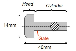 The project is at the design of the manufacturing mold, and mold designers forseen few manufacturing defects (warpage, voids, plastic deformation of degating (Malloy, 1994)). Part is parrallel to screw direction. The gate location is under the head of the part, and results in warpage. It is required to avoid flash allong the cylinder and the head.
3.1 Express the initial situation
The network representing any specific situation can be built with two different ways:
- Build the contradiction set from description of the situation (this depends on the ability of the designer to formulate contradictions);
- Build the contradictions based on the proposed knowledge structure (if it has been built beforehand).
- From formulated contradiction
The first way is to fomulate contradictions and to link them afterwards. After having gathered contradictions it is first necessary to put them in coherence with the proposed format (active, intermediary and evaluating parameters). Only six possibles types exist:
Table 1: Types of contradictions
|
Type |
Physical |
Technical 1 |
Technical 2 |
Picture |
|---|---|---|---|---|
|
1 |
Active |
Intermediary |
Intermediary |
|
|
2 |
Active |
Intermediary |
Evaluating |
|
|
3 |
Active |
Evaluating |
Evaluating |
|
|
4 |
Intermediary |
Intermediary |
Intermediary |
|
|
5 |
Intermediary |
Intermediary |
Evaluating |
|
|
6 |
Intermediary |
Evaluating |
Evaluating |
|
We propose the following examples, taken from the specific case:
- Type 1: If gate diameter is high then degating constraint is high and shear heat is high, but if gate diameter is low then degating constraint is low and shear heat is low;
- Type 2: If gate diameter is high then constraint of degating is high and material burning is satisfying, but if gate diameter is low then constraint degating is low and material burning is unsatisfying;
- Type 3: If gate location is top of head then warpage deformation is satisfying and microstructure homogeneity is unsatisfying, but if gate location is top of cylinder then microstructure homogeneity is satisfying and warpage deformation is unsatisfying;
- Type 4: If cavity surface temperature is high then bulk melt viscosity is low and cavity thermal shock is low, but if cavity surface temperature is low then bulk melt viscosity is high but cavity thermal shock is high;
- Type 5: If gate diameter is high then degating constraint is high and lack of material in produced part is satisfying, but if gate diameter is low then degating constraint is low but lack of material in produced part is unsatisfying;
- Type 6: If shear heat is high then lack of material in produced part is satisfying but material burning is unsatisfying, but if shear heat is low then lack of material in produced partis unsatisfying but material burning is satisfying.
Second, it is important to complete the built network based on the generic one, to check the completeness:
- check if any evaluating parameter of the generic set should be added as a required property of the final concept;
- check if any active parameters of the generic set should be added as something that can be changed to reach the objective;
- check if any phenomenon, explained through intermediary parameters in the generic network should be added to clarify the conflict’s reason;
- check if any generic conflict should be added to the specific network.
- From the generic network
The second way is to begin from the generic network and to select the portion representing the complexity of the specific situation (Figure 5):
Figure 5: Three steps of extraction

- Extract the objectives (1): extract the evaluating parameters that are important as goals of the design, identify both their current and required value. In our case: cost (low => low), simplicity of mold (high => high), microholes (much => no), microstructure homogeneity (high => high), amount of material (low => low), molecules burning (low => low), degating deformation (low => low), warpage deformation (high => low), material burning (low => low), lack of material in produced part (high => high).
- Extract the frontiers of the existing system (2): extract the active parameters that can be changed, those which currently have a value, and those describing standard alternative configurations. In our case: gate diameter (0,5mm), diameter of cylinder (3mm), diameter of head (14mm), length of part (40mm), gate location (top side of cylinder), part position in mold (parrallel to screw), number of mold plates (2), feeding mecanism (cold), structure of mold (first category), number of cooling channels, gate location (top of cylinder)
- Extract the portion of intermediary parameters that link the selected active and selected evaluating parameters (3). In our case: Contraint of degating, Adhesion melt-mold, Molecules diffusion, Location of sections in cavity, Compensation of thermal contraction, Molecules orientation, Shear heat, Cavity surface temperature, Skin viscosity, Cavity thermal shock
As a result of these three steps, we obtain the portion of the meta model describing the specific situation. The next step is to draw out of it the network of contradictions:
- Starting from required changes of evaluating parameters values (warpage deformation, microholes), get back to required values of selected active parameters (gate location) to reach evaluating parameters values and go back to worsen evaluating parameters (microstructure cohesion, Runner ejectability).
Finally, it is necessary to check if any foreseen specific conflict and difficulty is well represented in the contradiction network, and if the advantages and disadvantages of the current system compared to other configurations are well represented.
3.2 Synthesis to a key issue
Three types of contradiction network can be built during analysis of initial situation. The first is based on contradictions as milestones of the problem solving (one is solved, another appears, which is solved again, a new one appear, and so on); the second on contradictions describing alternative system configurations, each of them tackling the same key issue; and the last one on contradictions describing many needs, generated by many resources in a single system configuration. We do not consider here redundant contradictions, which is a semantic issue.The problem of treating contradictions network in classical TRIZ can be summerised in the following conflict: we should apply classical TRIZ solving tool (Matrix, Physical principles, ARIZ, sufield (Altschuller, 1973)) in order to direct the solving and because they are the most efficient solving tools, but we should not use them because we have a network of contradictions which cannot be solved separately. In order to treat this problem, we propose to synthesize the network to allow application of classical TRIZ tools:
Figure 6: Synthesis of network
 The «key issue» must have the following properties: its resolution leads to the greatest system improvement and it can be treated by classical TRIZ tools. We decided to use the pattern of contradiction for this key issue. This format is well suited for ARIZ, inventive principles of either technical or physical contradiction. The gap between the contradiction and sufield analysis will have to be filled by the solver. The synthesis we propose is based on two mecanisms, named selection (choose one contradiction out of a set) and convergence (merge many contradictions in a single one)
- Selection
The aim of this mecanism is to select, within a network of contradiction, the one that should be treated in priority. We propose a few selection criterias:
- Functional level of the elements described by the active parameters (Pahl&Beitz, 1996). In our case: if the part is changed, some contradictions related to the mold disappear, as the mold is developped according to the part;
- Priorities and weight of evaluating parameters (rigid constraint, flexible constraint, wishes, “bonus”…). In our case: warpage deformation is worse than flash; norms are firm; amount of material can be negotiated;
- Level of definition of active parameters (from conceptual to detailed level) (Pahl&Beitz, 1996). In our case: “mold structure has to be two plates to be simple but three plates to allow runner ejectability” compared to: “the gate diameter has to be large to allow good filling and small to avoid serious gate vestige”;
- Weight of active parameter on evaluating one. In our case: tuning the process (speed, pressure temperature…) can reduce flashes, but it will never be as reliable as a good mold opening direction; cooling system design can influence warpage deformation but in a less reliable manner than gate location;
- Number of contradictions the active parameter is concerned with. In our case: gate location has consequences on runner ejectability, microstructure homogeneity, warpage deformation, gate vestige, degating deformation whereas number of sliding affects only mold simplicity and flashes.
- Convergence
The basic idea of this mecanism is to use one single contradiction to represent more than one contradictions. We will present this idea with a particular example of two type 3 contradictions, named contradiction A and contradiction B.
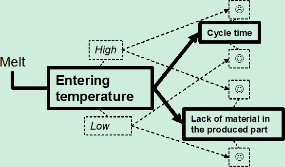
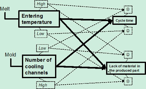
Contradiction A (Figure 7) is written with the classical format (Khomenko, 2002), and describes the influence of temperature of the melt at the entrance of the mold on both the cycle time and the good filling:
- If the parameter <entering temperature> is high, then the parameter <cycle time> will be unsatisfying and the parameter <lack of material in the produced part> will be satisfying;
- But if the parameter <entering temperature> is low, then the parameter <cycle time> will be satisfying and the parameter <lack of material in the produced part> will be unsatisfying.
Figure 7: Contradiction A
Contradiction B (Figure 8) is written with classical format too, and describes the influence of the cooling design on both the cycle time and the filling:
- If the parameter <number of cooling channels> is low, then the parameter <lack of material in the produced part> will be satisfying and the parameter <cycle time> will be unsatisfying;
- But if the parameter <number of cooling channels> is high, then the parameter <cycle time> will be satisfying and the parameter <lack of material in the produced part> will be unsatisfying.
Figure 8: Contradiction B

As they have the same evaluating parameters, it is possible to join them (Figure 9):
Figure 9: Joining
Second, we can identify the intermediary parameter (see (Malloy, 1994)) thanks to which we can converge these two contradictions (Figure 10). The more the viscosity of bulk melt is high during filling, the less time will be required to solidify the part, but the harder the material will flow:
Figure 10: Intermediary contradiction
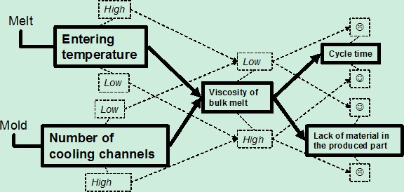
Contradiction A is adapted from Figure 7 to introduce the intermediary parameter:
- If the parameter <entering temperature> is high, then the parameter <viscosity of bulk melt during filling> is low, and then the parameter <cycle time> is unsatisfying and the parameter <lack of material in the produced part > is satisfying;
- But if the parameter <entering temperature> is low, then the parameter <viscosity of bulk melt during filling> is high and then the parameter <cycle time> is satisfying and the parameter <lack of material in the produced part> is unsatisfying.
Contradiction B is adapted from Figure 8 also:
- If the parameter <number of cooling channels> is low, then the parameter <viscosity of bulk melt during filling> is low, and then the parameter <cycle time> is unsatisfying and the parameter <lack of material in the produced part > will be satisfying;
- But if the parameter <number of cooling channels> is high, then the parameter <viscosity of bulk melt during filling> is high, and then the parameter <cycle time> is satisfying and the parameter <lack of material in the produced part> is unsatisfying
Hence, we can converge those contradictions in the following one (Figure 11):
Figure 11: Converged conflict
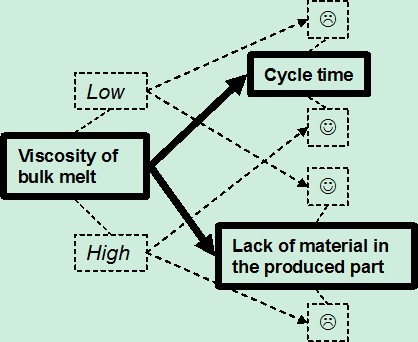 The converged conflict of Figure 11 is expressed with the classic format:
- If the parameter <viscosity of bulk material during filling> is high, then the parameter <cycle time> will be satisfying and the parameter <lack of material in the produced part> will be unsatisfying;
- But if the parameter <viscosity of bulk material during filling> is low, then the parameter <lack of material in the produced part > will be satisfying and the parameter <cycle time> will be unsatisfying;
The same converging idea can be used for more than two contradiction, and for any type of contradictions listed above. The single condition is that contradictions have common portion of technical parameters (polycontradiction). This condition is not so restrictive because if contradictions are independent they do not need to be synthesised. The main advantage of this mecanism is that we do not discard any contradiction but on the other hand, the disadvantages are the followings:
- We do not take their relative weight into account;
- There can be more than two system configurations considered and more than two evaluating parameters to take into account into following ARIZ application;
- It is specific to a kind of contradiction links (they have common technical parameters).
- Conclusions
We presented two main mecanism to synthesize a contradiction network, the first is a selection and the second is a convergence. In real project those two mecanism have to be used simultaneously to reduce complexity of the situation representation without reducing the performance of the system improvement. However, our proposal does not eliminate human decisions: the two mecanisms might guide to more than one “key issue” and the solver will have to choose!
Two main issues remain:
- Mental inertia: designer will select the conflict that he feels more confident with, and can therefore miss powerful solution;
- Tests have to be done to find which criteria is the most reliable.
4. Conclusions
In this paper we presented a way to structure knowledge before tackling the problematic situation. It is based on three families of parameters, with which contradictions are formulated. We proposed two mechanisms to adapt the resulting contradiction net to typical TRIZ tools. One of the advantage if the possiblity to use a common “knowledge langage” for both problem free design projects and problem solving process. This will be very helpful to fully integrate TRIZ in any design process (from both industrial and academical point of view). However, the representation mode based on three families of parameters should be adopted during problem solving even if the knowledge stock is not present beforehand but gathered during problem solving.
Nevertheless, few points still need to be improved:
- the graphical representation of networks is not yet optimised;
- use of the proposed selection criterias has to be sharpen;
- semantics of generic parameters of any of the families might have to be adapted to the specific application: the distance from generic to specific is not only values of generic parameters.
5. Acknowledgement
We wish to acknowledge Pr Emmanuel Caillaud and Dmitry KUCHARAVY for their help in our researches. We are also very thankful to “Region Alsace” who supports our TRIZ research.
6. References
- (Altschuller, 1973) Altschuller, G.A. 1973. Book “The innovation algorithm”. Technical Innovation Center.
- (Beiter et al, 1995) Beiter, K, Cardinal, J, Ishii, K. 1995. Conference proceeding. “Design For Injection Molding: Balancing Mechanical Requirements, Manufacturing Costs, and Material Selection”. In ASME Computer Integrated Concurrent Design Conference, Boston.
- (Chakravarty, 2001) Chakravarty, Amiya K. Journal article. “Overlapping design and build cycles in product develoment”. In European journal of operational research, vol 134, p. 392-424.
- (Eltzer, 2004) Eltzer, T, Cavallucci, D, Lutz, P, Caillaud, E. 2004. Conference proceeding. “Problem formulating for inventive design - Application to molding technology”. In CIRP04, Cairo.
- (Holtj, 1992) Holtj, K. 1992. Journal article. “Computer-aided creativity in engineering design”. In Journal of engineering design, vol 4, issue 4, p.371-376.
- (Khomenko, 2002) Khomenko, Nikolaï, Kucharavy, Dmitry. 2002. Conference proceedings. “OTSM-TRIZ problem solving process: Solutions and their classification”. In ETRIA02, Strasbourg.
- (Malloy, 1994) Malloy, R.A. 1994. Book. “Plastic part design for injection molding”. Hanser / SPE.
- (Pahl&Beitz, 1996) Pahl, G and Beitz, W. 1996. Book. “Engineering design: A systematic approach”. Springer.
- (Rosato, 1995) Rosatos. 1995. Book. “Injection molding handbook”. Chapman et Hall.
- (Shaw, 1986) Shaw, M.C. 1986. “Creative design”. In CIRP Annals, vol 35, issue 2, p.461-465.
- 71339 reads

Recent comments
13 years 13 weeks ago
14 years 13 weeks ago
14 years 13 weeks ago
14 years 13 weeks ago